Note: Though the instructions tell you to use the 10uF smoothing cap to connect the sound output to the RF box, but connecting it to the left leg of C33 (right next to the RF modulator) works better (it’s closer to your output if you’re adding the jack to the right side of the case) and doesn’t require the use of the capacitor.
In fact, the only connection you’ll want to connect in the modulator is the video connection, and it’s much easier to connect to the solder point to the left of the one they show in their diagram.
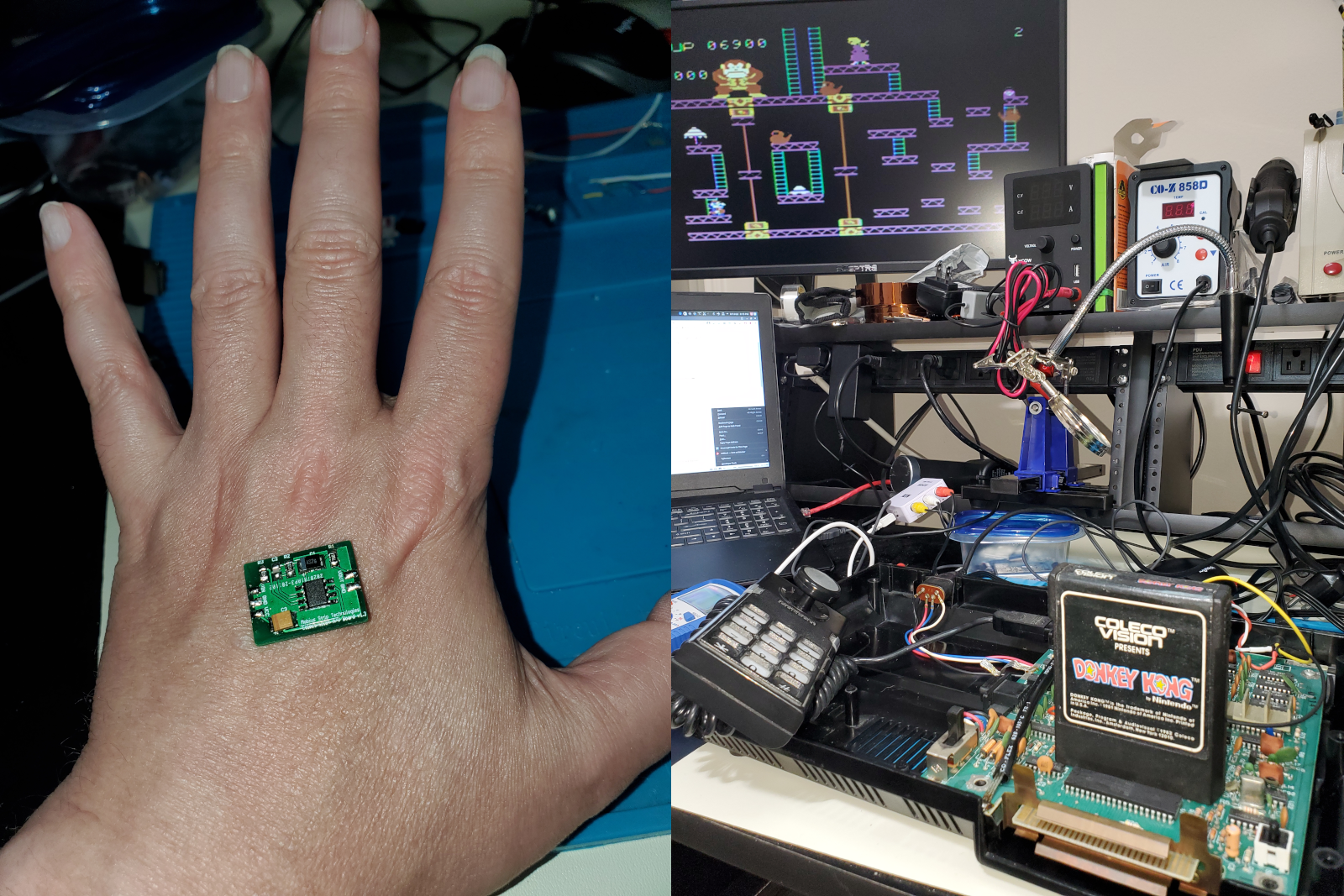
Ground can be found on the board just left of the BIOS chip, and VCC can be pulled from the right edge of WJ2. Those two points will probably be much closer to where you sit the mod chip, and it makes it easier for you to snake the one video wire out of the modulator housing so that you don’t need to trim any of the metal from the housing.
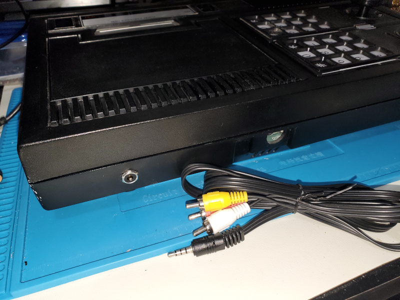
One thing I did have to trim was the RF shielding that covers the entire motherboard. But, I just cut off a small rectangle in the back so that the output jack and wires could make it through. Be sure to take a file to the edges after you snip it or else its sharp-as-a knife edging could cut through your wires and ground something out.